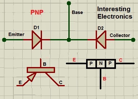
This post is about troubleshooting the unknown transistor.It helps you to identify a transistor whether it is PNP or NPN. It is very easy to identify. Here, I will discuss the procedure how to do that.
A transistor is actually like the figures below,
 |
| Fig(a) |
 |
| Fig(b) |
 |
| Fig(c) |
Fig(a) & (b) are for PNP and NPN transistor respectively. The Transistors are actually the two diodes connected together like the above figures. It's almost like a diode test. For PNP transistor, if you connect the multimeter positive to the base and negative to emitter and collector separately, you will see a reading of resistance. And for NPN if you connect a the multimeter negative to base and positive to emitter and collector separately, you will see a reading of resistance. Now for testing the transistor follow the step below,
- Take your multimeter (Digital or Analog) and set it to resistance measuring mode or continuity test mode at a medium range.
- Take your Transistor and mark the pin 1, 2 & 3 as you like. This is only for your notation to describe or identify. See figure (c).
- Now Just connect as below and observe the readings.
b). Multimeter pos (+) to 1 & Neg (-) to 3;
c). Multimeter pos (+) to 2 & Neg (-) to 1;
d). Multimeter pos (+) to 2 & Neg (-) to 3;
e). Multimeter pos (+) to 3 & Neg (-) to 1;
f). Multimeter pos (+) to 3 & Neg (-) to 2.
Decision:
If you get any positive data for above a & b or, c & d or, e & f observations from step 3, make sure that your transistor is a PNP transistor.Because, with a PNP transistor the base will have two diodes facing towards it.On the other hand, if you get any positive data for above a & f or, b & d or, c & e from step 3, make sure that your transistor is a NPN transistor. Because, with an NPN transistor the base will have two diodes facing away from it.
The above procedure is based on using a ohmmeter. If you have a multimeter with diode test mode. Then another criteria can be done. Set your multimeter to diode test mode. connect as below,
(i) Pin 1 to Positive & Pin 2 to Negative;
(ii) Pin 2 to Positive & Pin 1 to Negative;
(iii) Pin 1 to Positive & Pin 3 to Negative;
(iv) Pin 3 to Positive & Pin 1 to Negative;
(v) Pin 2 to Positive & Pin 3 to Negative;
(vi) Pin 3 to Positive & Pin 2 to Negative.
Observe the readigs. You can see the readings as volt. Since there is two diode on a transistor, the voltage you can see approximately 0.7 V ( Silicon) or 0.3 V (Germanium). If you get values for observations (i) & (iii) or, (ii) & (v) or, (iv) & (vi), make sure that your transistor is a PNP transistor.(ii) Pin 2 to Positive & Pin 1 to Negative;
(iii) Pin 1 to Positive & Pin 3 to Negative;
(iv) Pin 3 to Positive & Pin 1 to Negative;
(v) Pin 2 to Positive & Pin 3 to Negative;
(vi) Pin 3 to Positive & Pin 2 to Negative.
If you get values for observations (i) & (vi) or, (ii) & (iv) or, (iii) & (v), make sure that your transistor is an NPN transistor.
Great! I will try this using our recently bought digital multimeter from Fluke Philippines.
ReplyDeleteYou did an excellent job on this post!
ReplyDeleteIn this article, you will learn how to make a rechargeable digital multi-meter from PVC pipe sheets at home. We will use PVC pipes sheets to make a multi-meter box. You can easily make a digital multi-meter at home in simple steps.